Posts by graysters

Caution: Non registered users only see threads and messages in the currently selected language, which is determined by their browser. Please create an account and log in to see all content by default. This is a limitation of the forum software.


Also users that are not logged in can not create new threads. This is a, unfortunately needed, counter measure against spam. Please create an account and log in to start new threads.

Don't Panic. Please wash hands.

    Latest update:


    Urgh... This board is in an awful state. Whatever was spilt and left on the board has damaged a number of traces to the CPU pin vias, on both sides of the board... I have been tracing the various signals between the CPU, the 'Data' CPLD and... Address/clock/other magic? CPLD and think I have patched up the data bus signals and address lines, though can't find a CPU->CPLD connection for [A27:A29] & A31, not sure if these are unused as it's outside the 128MB address space? (Though I note A30 goes from CPU to CPLD via resistor R11). Where I'm struggling is identifying opens on traces & CPU pin connections that are *underneath* the CPU.


    I won't presume to ask for a schematic, but to at least save me having to de-solder the CPU, I would be ever so grateful if you could share a photo/image showing the top-side of the board around the CPU so that I can at least visually trace the signals running under the CPU, and patch any remaining opens.


    All the best,


    Graysters

    First of all, the picture you've posted shows more than "corrosion" - it appears like mechanical damage, but that green-ish residue looks like the thing has been stored in a humid basement for years.

    Indeed. Not pretty is it? Amazing how it got so bad in such a relatively short period (5 years tops, right?)


    Data pins of the clock port are unbuffered CPU data lines. If they are shorted "somewhere", the computer won't start. And it may also explain why the data CPLD is gettig hot.

    Noted. Right, I'll get probing!

    I've put the FPU to one side for the minute, and returned to the board, and there's a small amount of progress... I managed to get hold of a stereo microscope to check out the soldering a bit more closely. (pics below are just with my camera, I tried a 'through the microscope' shot, but it wasn't particularly clear). First I took a look at the FPU socket....


    It's far from a perfect solder job, but not horrendous and crucially no obvious shorts to any traces... however, I took a look at the expansion slot connector soldering and was struck by significant corrosion due to (I suspect) rather liberal application of flux which wasn't thoroughly cleaned off (not saying this is due to icomp! It may have been 'overspill' when the FPU socket was soldered by previous owner!). I've given it a gentle clean with IPA, and the damage is mostly just stripped solder mask, but in probing, I have found 3 shorts on the traces that snake around the pins. 2 of these appear to be data pins that go to the clock-port, which shouldn't stop the card starting, so I will tackle at some point, but a third was from the reset pin(!) so a bit more crucial!


    I've now added a patch wire to reconnect this.


    No change in behaviour when re-installed though (testing at various mm of extraction as usual!) There's no other obvious issues on the back-side of the board, but I've yet to do a full 'ring out' of the expansion port connector. My concern is that the corrosion may extend to the top side of the board which will be a pain to get to as it is under the plastic expansion socket connector against the PCB. I don't particularly fancy desoldering the whole connector! I will try and trace all the wires I can see on the topside first...


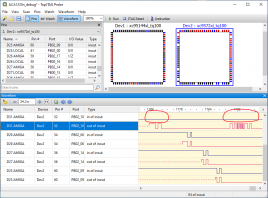
    On the JTAG front, there's a limited amount of progress... The JTAG cable I ordered arrived but frustratingly... it was mislabelled by the seller as a Xilinx platform cable, but is in fact a Digilent JTAG-USB cable, which only supports basic chain-tracing for XC9500(XL) series CPLDs, and not much else. However, with this, I was able to do a chain test in iMPACT, and both CPLDs do indeed show up:


    That's more than I expected, and tells me that the data CPLD is not entirely dead... though, given how much hotter the data CPLD is than the other CPLD, even when just sat idle, I still strongly suspect a fairly fatal internal short necessitating replacement!


    Anyway... New JTAG cable ordered from a seller that assures me that it's a genuine clone of a Xilinx platform cable (if that's not a contradiction in terms!) This should be compatible with JTAGLive or Topprobe to allow me to wiggle the I/Os and see exactly what's working or not...


    Determined to revive this board!

    Thanks Jens.


    Yes I think I saw some of the same Aussie's Youtube videos which convinced me that the scope should be OK. Obviously not up there with the Agilent/Keysights, but seems to have everything I think that I could need for a while at least.


    Thanks for the suggestion, I'll have a good inspect around the existing FPU socket soldering. Could probably do with a decent stereo microscope... hmm I feel another purchase coming on!


    Interestingly the card came with an FPU installed in the socket, but I removed it to help with debug (Obviously the board is still not working with/without it). I did note that the FPU clock jumper had not been bridged (and by the looks of it had never been). Given that the 12V supply wire prevents a crystal easily being installed, I can only assume that the FPU was never used as it would never have got a clock! Odd.


    I might have a look at the supplied 'FPU' chip in a bit more detail, at least to see if any of the common pins (e.g. ground/supply) have continuity where expected based on the 68882 pinout. Just to check it's not obviously an outright rebadged different chip. Here's a pic of it. I doubt there's any easy way of telling by it's exterior whether or not it's obviously a fake?:


    Anyway, I'll inspect around the FPU pins this evening and wait patiently for my JTAG cable to arrive to debug further.


    Thanks again Jens for your support. It's very much appreciated.

    Hi Jens,


    I was looking out for an Agilent scope, like the one you mentioned, but in the end I managed to get hold of an ex-demonstrator model Rigol MSO1104Z-S (mixed signal 4ch ana/16ch dig, 100MHz 1GSps), for a particularly good price, so went with that!


    I also have a Xilinx (well... 'compatible') platform cable usb JTAG adaptor on it's way to me to check out the JTAG chain, to see if there's any life in the CPLD(s), but my suspicion is that the data CPLD at least is, to use a technical term, 'knackered'!


    In the mean time, I fired up the scope to get a better look at the crystal output. Seems like a fairly solid 55.5MHz signal coming from it, so I suspect we can rule that out as the issue (see below)?


    While I wait for the JTAG adaptor to arrive, Is there anything else on the board worth probing with my new scope, to assist with the debugging my end (any pins on the other CPLD by the crystal worth probing for signs of life)?


    I guess it's just putting off the inevitable, but as I'm sure you can appreciate, I'd rather be doing something practical at my bench, rather than scratching my head trying to work out how to navigate shipping companies and customs to be able to get this board to you and back without incurring the full board value VAT cost on the way back!

    Hi Jens,


    If you can do a boundary scan and wiggle on each pin high/low, read it back and compare what you've written - that would make things easier for us, but since there's nothing you can do to repair it (the jedec file of this chip is not public), it'll come down to "ship to Germany" anyway.


    I'll see if I can get into the office to try this out, but I guess if one of the CPLDs is sufficiently broken, the whole JTAG chain will be broken so scan may not tell us anything other than 'something's broken'. As you say, the net result will likely be 'ship to Germany' anyway, but if I can help in the diagnosis process in anyway, I'm more than happy to.


    If you can, please measure the 55MHz oscillator. You described mechanical damage before, and you have to treat these oscillators like mechanical parts. They are sensitive to shock and will fail if they're falling hard

    With my limited home testing equipment (100Msps logic analyser), I've ascertained that the crystal output is oscillating at around 50MHz(ish).. so I can believe it is running at 55MHz but can't get much more accuracy until I get to the office... That said, I'm very close to ordering myself a decent oscilliscope to do this sort of thing at home... this might just push me over the edge to ordering one!!


    The 9572XL chip is 4,70 EUR, and exchanging the chip including JTAG programming is 28,- EUR. Plus your local VAT plus shipment (DHL actually charges an extra Brexit fee!), will still be much cheaper than a new card. However, this is only an estimate based on the assumption that only the data-CPLD is dead.


    That seems more than reasonable, and I'd be more than happy to pay this for (or x2 if both CPLDs need replacing), so I would be happy to proceed with this.


    Cheers,


    Graysters

    Hi Jens,


    Any insight into the board's history from the Warranty ID? (VT4F3). Would it be worth me waiting till I get into work to hook up via JTAG to check the CPLDs, or just look to return for repair? I can probably source and replace the CPLD(s) myself, but obviously the magic is in the jed files, which I totally understand you're not going to want to be sending out!


    I've started looking at the customs situation regarding UK->EU->UK repairs, and it looks like the VAT/Duty can be kept to a reasonable level by using 'outward processing' which seems specifically setup for exactly this situation. Details here:

    https://www.gov.uk/guidance/us…cess-or-repair-your-goods'

    Based on this it seems that the VAT/Duty is payable only on the cost of the repair (and postage/packing), rather than the full price of the repaired goods. I just need to look into the paperwork


    If you could let me know what the cost of repair would likely be (either here, or by private message), I would be most greatful.


    Thanks,


    Graysters

    Hi Jens. Thanks again for the swift response!


    The regulator is measuring 3.294V, so doesn't seem too far off. Regarding JTAG access, I might have been able to do this... if I could get into the office, (I'm an ASIC implementation engineer, and have done a little Xilinx CPLD programming myself... but I'm nowhere near an expert!)


    Warranty ID is VT4F3


    Sadly I'm in the UK (Cambridge).... so I was in Europe until about 6 weeks ago... :( I certainly didn't vote for Brexit!!


    I'd still be interested in exploring a repair if the price is reasonable and customs can be negotiated.


    Cheers,


    Graysters

    Hi There!


    I have recently purchased a second hand ACA1233n-55 which is non-functional. (This was the one that I mentioned yesterday had the damage to the cap C85, which has now been replaced, along with the 5V regulator, thanks to Jens pointers as to the value of the Cap!)


    Having successfully sourced and replaced the C85 cap, the board is still not working (blank screen, power light on, but no other activity), even after various cleanings of the connector and repositioning the card. (I also have a working ACA1221 which works fine, so I don't suspect the edge connector being an issue.)


    One thing I did notice was that the ACA1233n CPLDs were getting very warm to the touch with the power on. Not 'too hot to touch', but certainly 'uncomfortable to hold your finger on!' The one by the CPU slightly hotter than the one by the crystal. I wanted to check whether that was normal, or a likely sign that the CPLD(s) are faulty, or whether it might point to another issue I can investigate?


    As mentioned yesterday, this card is second hand and totally out of warranty. The chap I purchased this card from assures me that it was working prior to the cap and regulator being knocked off, but I obviously can't prove this. Would love to get this working if I can, but wanted to check whether continued debugging effort was justified.


    Out of interest, do you offer an out-of-warranty repair service on these cards?


    Cheers,


    Graysters


    (FWIW this is with a recapped B2 motherboard A1200 with timing fixes applied and powered by an original Amiga 500 4.3A supply.)

    Hi There,


    I have a ACA1233n-55 that has sustained some damage to the capacitor C85 during fitting (the one that the additional 5V regulator is attached to), as such I am looking to replace this capcitor, and was wondering if you would be so kind as to tell me what size/value capacitor I should use to replace it with.


    Many thanks in advance!