

Hi all!
First of all, I just received and installed my MK3, so thanks for it, for the fast delivery.
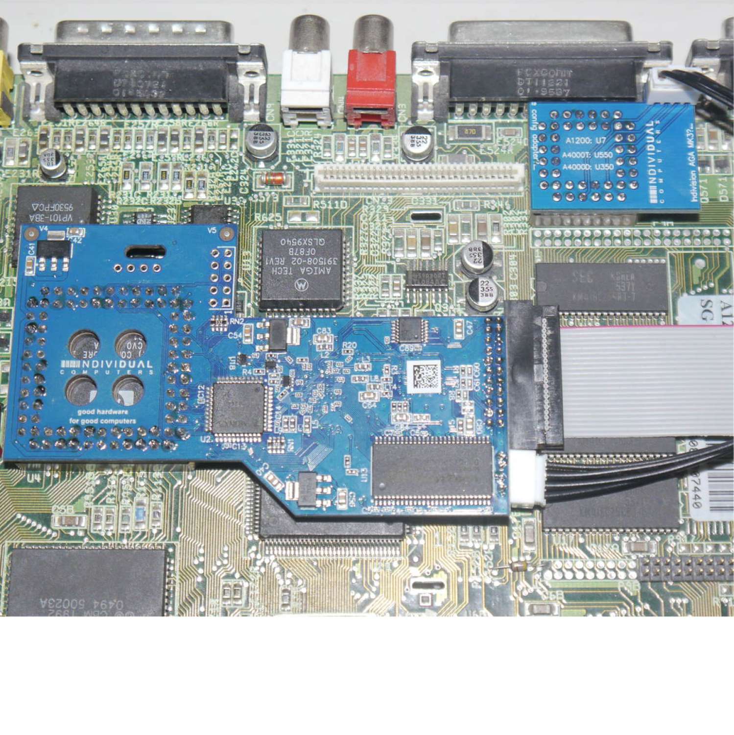
As I said, I already mounted it on my A1200, not without some doubts. For example, while the installation of the main board itself on top of the LISA chip is pretty clear, the installation of the tiny board on the CIA chip is not so clear: that arrow mark on the tiny CIA board should coincide with the mark on the CIA chip itself, but it does not, and the image on the installation manual does no help much, is way too dark. Curiously, the image corresponding to the A4000T installation is pretty clear and a detailed close-up.
A friend told me that I should look for the indented corner on the chip and make the tiny CIA board coincide with it, and since I am a "measure three times, cut one" kind of guy, I looked also for images in your Indivision MK3 shop page, and fortunately there was a very clear and detailed image on how to install it, but it should be clear also in the manual and it is not.
Now it's time to try it, let's see how it works.
Saluditos,
Ferrán.
Caution: Non registered users only see threads and messages in the currently selected language, which is determined by their browser. Please create an account and log in to see all content by default. This is a limitation of the forum software.
Please understand that you need to create an account to be able to post, guest posting was disabled as an anti spam measure.